Stencil Shadow Volumes
By Jérôme 'JeGX' GUINOT - The oZone3D Team
jegx [at] ozone3d [dot] net
Initial draft: September 21, 2005
Translated from french by Jacqueline ESHAGHPOUR - jean25 [at] freesurf [dot] ch
1 - Introduction

Shadows and shading are a particularly active domain in 3D graphics. Shading is the essence for reality in a 3D
scene. Shadows are the result of interaction between the light and the objects. Shadows makes it possible to show the effects of depth
in the scene and more especially to confer some weight to 3D objects (the observer does not get anymore a "floating impression").
Shadows are classed in two main categories:
- soft shadows
- hard shadows
In everyday reality, hard shadows do not exist; only soft shadows really exist. But in some cases, and seen from a
distance, soft shadows look like hard shadows. All this is fine, but necessitates further explanation. A shadow
is considered soft when the passage from the shadowed zone to a lit zone is progressively made. This transition zone
is known as
penumbra.
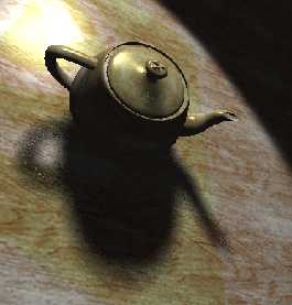
fig. 1 - Soft shadowIn figure 1, the soft shadow is clearly visible. On the contrary, a shadow is called "hard" if the passage from the shaded
zone to the lit zone is made without transition as shown in figure 2.
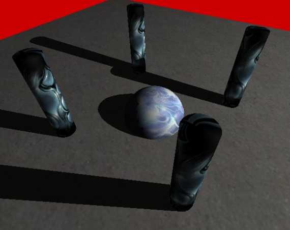
fig. 2 - Hard shadowSoft shadows are very realistic but are often relatively complex to reproduce in real-time 3D. The algorithms of soft shadows
have started to arrive but require tough 3D cards (such as GeForce 6800 GT or better still GeForce 7800 GTX). Hard-shadows,
however, are far more rapid to generate and have become extremely common in recent video games. But there is a game which really put
hard shadows to the forefront:
Doom 3.
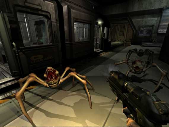
fig. 3 - Doom3 - Copyright 2004 Id SoftwareThe technique used in Doom 3 to create these hard shadows bears a precise name:
Stencil Shadow Volumes.
The stencil, more known under the name of stencil buffer, is a particular memory zone on the graphics card which is used
for all kinds of special effects, amongst which shadow volumes. There is no question of detailing its function as one would need
to enter into the heart of OpenGL or of Direct3D to really understand. What it is important to know is that, without the presence
of this particular memory zone, shadow volumes would simply not exist.
We will now see how all this works as Demoniak3D runs the Stencil Shadow Volumes...

In the global functioning of the stencil shadow volumes, there are three performers:
- the light
- the shadow-caster
- the shadow-receiver
Light is generally a positional type source (or OMNI).
The
shadow-caster is the shadow thrower: it is the object which will
block the light and create the shadow. The
shadow-receiver is
an object which "receives" the shadow, or to be more precise, it is the object
which is totally or partially deprived of light.
The shadows are said to be "volumic" simply because the shadow-caster will
create a volume of shadow where the objects therein will not receive any light. Figure
4 shows the volume of shadow generated by a torus:
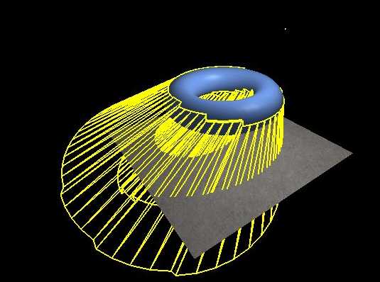
fig. 4 - Shadow VolumeThe principle of shadow volume is to detect the silhouette of the object from
the source light point of view and to project this silhouette in the
direction definded by the vector between the
light and the
object. The projection
of the silhouette will form the shadow volume.

Now that we have seen the basic principles of shadow volumes, let us get down to the
practical side. In Demoniak3D’s operating, shadow volumes only work with meshes or with models as these are the only 3D objects
which have a "reality" (virtual nonetheless…) in a 3D scene.
Therefore, the use of shadow volumes is easy, as all one has to do is to set to "TRUE" the shadow_caster attribute
of the mesh or model nodes. Really simple!
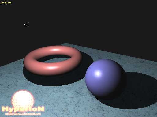
fig. 5 - The example projectThe following script (script 1) allows one to obtain the scene in figure 5. This
scene contains a floor which acts as the shadow-receiver, and two 3D objects (2
models) which are the shadow-casters. The little white wire sphere represents
the position of the light source.
<?xml version="1.0" encoding="ISO-8859-1" standalone="yes"?>
<hyperion version="1.0">
<!--
====== SCENE =======================================
-->
<scene name="StencilShadowVolume_Demo_1"
       display_fps="TRUE"
	   vsync="TRUE"
	   show_ref_grid="FALSE" >

	<window_size width="1024" height="768" />
	<global_ambient_light r="0.2" g="0.2" b="0.2" />
	<background_color r="0.1" g="0.1" b="0.1" />
</scene>

<!--
====== LIGHT ==========================================
-->
<light name="Light_01" render="TRUE" >
	<position x="0.0" y="150.0" z="100.0" />
	<ambient r="0.2" g="0.2" b="0.2" a="1.0" />
	<diffuse r="1.0" g="1.0" b="1.0" a="1.0" />
	<specular r="1.0" g="1.0" b="1.0" a="1.0" />
</light>

<!--
====== CAMERA =========================================
-->
<camera name="Main_Camera"  >
	<position x="30.0" y="100.0" z="200.0" />
</camera>

<!--
====== FLOOR =========================================
-->
<texture name="floor_tex"
         filename="data/Speckles_LightBlue_df.dds" />

<material name="floor_mat" >
	<ambient r="0.7" g="0.7" b="0.7" a="1.0" />
	<diffuse r="0.9" g="0.9" b="0.9" a="1.0" />
	<specular r="0.1" g="0.1" b="0.1" a="1.0" exp="10.0" />
</material>

<mesh name="floor" shape_type="PLANE"
      lighting="TRUE" texturing="TRUE"
	  polygon_mode="SOLID" use_vbo="TRUE" >
	<plane x_size="500.0" z_size="500.0"
	       num_segs_x="20" num_segs_z="20" />
	<attach_material name="floor_mat" />

	<texture material_name="floor_mat"
             texture_name="floor_tex"
             texture_unit="0"
             u_tile="1.0" v_tile="1.0" />
</mesh>

<!--
====== TORUS MESH =======================================
-->
<material name="mat_torus" specular_exp="60.0">
	<ambient r="0.3" g="0.3" b="0.3" a="1.0" />
	<diffuse r="0.9" g="0.5" b="0.5" a="1.0" />
	<specular r="0.6" g="0.6" b="0.6" a="1.0" />
</material>

<mesh render="TRUE" name="torus" shape_type="TORUS"
      lighting="TRUE" use_vbo="TRUE"
      improve_specular_highlights="TRUE"
	  shadow_caster="TRUE" remove_seam="TRUE" >

	<torus vertex_density="50"/>
	<position x="-70.0" y="50.0" z="0.0" />
	<attach_material name="mat_torus" />
</mesh>


<!--
====== SPHERE MESH =======================================
-->
<material name="mat_sphere" specular_exp="60.0">
	<ambient r="0.3" g="0.3" b="0.3" a="1.0" />
	<diffuse r="0.5" g="0.5" b="0.9" a="1.0" />
	<specular r="0.6" g="0.6" b="0.6" a="1.0" />
</material>

<mesh render="TRUE" name="sphere" shape_type="SPHERE"
      lighting="TRUE" use_vbo="TRUE"
	  improve_specular_highlights="TRUE" shadow_caster="TRUE"
	  remove_seam="TRUE"  >

	<sphere radius="40.0" stacks="40" slices="40"/>
	<position x="70.0" y="40.0" z="0.0" />
	<attach_material name="mat_sphere" />
</mesh>

</hyperion>
Script 1 – StencilShadowVolume_Demo_1.xmlScript 1 does not present any particular difficulty, but it introduces a few novelties and subtleties.
The global ambient light attribute of the scene node allows colour specification of the scene’s global ambient
light in the absence of all light sources (the light nodes). This specification is important because the shadow volume
and the objects (the shadow-receivers) are only lit by this global ambient light. By default, in Demoniak3D, it is initialised
at R=0.1, G=0.1 and B=0.1, thus a very low value.
One must also pay particular attention to the choice of the ambient light and to the materials. This is primordial in
order to obtain a good self shadow. For memory, the self shadow of an object is the part of the object which does
not receive direct (or diffused) light from a light source, and which is solely illuminated by ambient light from this same light
source. In the case of the blue sphere in figure 5, the self shadow is the dark part (but which one can distinguish), whereas the
blue part (with the whitish reflection) is that which is directly exposed to the light source and which receives diffused
(and specular) light.
But the choice of the ambient light and material components is important for yet another reason: to mask and hide the
rendering of the silhouette’s shadow. Figure 6 shows the rendering of the scene with a bad choice of ambient
components, and also a sphere containing few polygons.
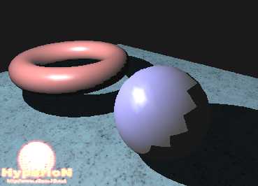
Fig.6 – Bad adjustment of the ambient componentsIn the scene in figure 6, the parameters of the sphere within the mesh
node are the following:
<mesh name="sphere" shape_type="SPHERE" >
	<sphere radius="40.0" stacks="20" slices="20"/>
	</mesh>
This low polygon density provokes a hideous aliasing effect on the shadow side of the sphere. It is one of the
inconveniences of the stencil shadow volumes: the algorithms require a fairly dense polygon object in order to obtain a good
silhouette.
The ambient material components of the sphere and of the light, as far as they
are concerned, are resolved in the following manner:
<material name="mat_sphere" >
	<ambient r="0.5" g="0.5" b="0.5" a="1.0" />
</material>

<light name="Light_01" >
	<ambient r="0.5" g="0.5" b="0.5" a="1.0" />
</light>
These adjustments accentuate the rendering of the shadow volume on the sphere
itself. The first way to ameliorate the visual aspect of the scene in figure 6 is to correctly adjust the ambient components of
the light and the sphere’s material. The following adjustment, while
maintaining the low density of the sphere’s meshing, gives the result seen in
figure 7:
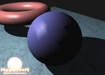
Fig.7 – Good adjustment of the ambient componentsThis is becoming excellent! But, if you look closely, you will notice that there still remains an aliasing effect due to the
low density of the sphere’s meshing. (figure 8).
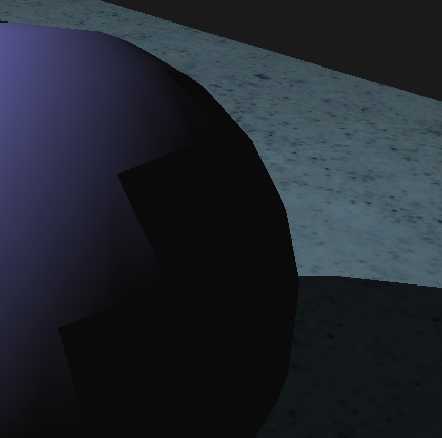
Fig.8 – One still notices the aliasing effect...The solution to making this aliasing effect completely disappear is to increase the density of the mesh:
<mesh name="sphere" shape_type="SPHERE" >
	<sphere radius="40.0" stacks="50" slices="50"/>
	</mesh>
With these adjustments, the aliasing effect has become imperceptible, as shown in figure 9.
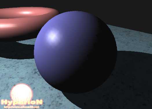
Fig.9 – The aliasing effect has disappearedThis example shows that in order to obtain a rendering based on stencil shadow
volume, the 3D objects must have a certain mesh density, and that the
material and light ambient components are adjusted to relatively low values.
This low value of the ambient components is responsible for making scenes which use
ambient components rather dark. The game Doom 3 is a perfect example of this!

As usual in realtime 3D, the most spectacular graphic effects have their price! The most
constraining rule concerns the modelling of 3D objects. All 3D models are not candidates to becoming a
shadow-caster. In order to project a shadow volume, the meshes forming a model must be closed.
But what is a closed mesh?
Before giving a definition, let us just give a little reminder concerning the
structure of the mesh surface. A mesh is a surface composed of triangular
polygons. Each triangle represents a surface and is composed of 3 vertices and 3
edges. The simplest mesh one can make is a... triangle.
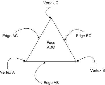
Fig.10 – The triangle: base component of a meshA mesh is said to be closed if each edge is shared by two sides (each edge
having two adjacent sides).
The sphere is the perfect example of a closed surface. You cannot find an edge
which does not belong to the same side. A plane, to the contrary, is the typical
example of an unclosed surface (or open surface!): each edge belongs to the one
and only side.
An edge which only has one side is called a crack. Therefore a mesh containing
cracks cannot correctly project shadow volumes. This limitation comes from the silhouette
detection algorithm which, in order to work, requires closed surfaces.
The model of the teapot, which one can rapidly generate with 3D Studio MAX for
example, has cracks. The teapot lid is an unclosed surface. The result of these
cracks is seen in figure 11.
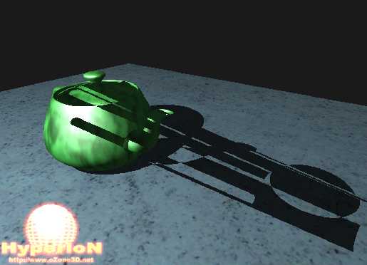
Fig.11 – Unclosed surfaces cause visual defectsTherefore modelling with the aim of projecting shadow volumes must be made
keeping in mind the obligation of a closed surface. For instance, if you wish to have a flat
surface (such as a wall) as a shadow-caster, you only need to model a box which
is very thin. Seen from a distance, it resembles a plane but for the shadow
volume algorithm which sees the model closely, the box is a closed surface.
Another obligation to take into consideration is the number of light sources.
The stencil shadow algorithm is by nature a multi-pass algorithm.
That means that the whole scene is rendered for each light source. If the scene is filled with polygons, the
number of FPS (Frames Per Second) runs the risk of falling drastically! For example: if you
have a scene composed of 100000 polygons and 3 light sources, there will be
roughly 300000 polygons rendered at each frame.
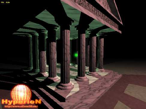
Fig.12 – Model lit by 2 light sources – Code Sample 70

 | Accompanying project |